logo
player background
live avator

5s
Total
0
Today
0
Total
0
Today
0
  • What would you like to know?
    Company Advantages Sample Service Certificates Logistics Service
Online Chat WhatsApp Inquiry
Auto
resolution switching...
Submission successful!
Zhenglan Cable Technology Co., Ltd
Products
News
Home >

China Zhenglan Cable Technology Co., Ltd Company News

Contacts
Contacts: Miss. Linda Yang
Fax: 86-371-61286032
Contact Now
Mail Us

The effect of Short-Circuit Current in Cables

A short circuit occurs when two points with different potentials are improperly connected directly or by a conductor with very low impedance (or resistance) in a normal circuit. Short circuits generate very large currents, often damaging electrical equipment or causing fires. In power systems, abnormal connections (short circuits) between phases or between a phase and ground (or neutral line) can result in extremely large currents flowing through them. These currents are much greater than the rated current and depend on the electrical distance between the short-circuit point and the power source. For example, when a short circuit occurs at the generator terminal, the maximum instantaneous short-circuit current flowing through the generator can reach 10 to 15 times the rated current. In large-capacity power systems, short-circuit currents can reach tens of thousands of amperes. This can have serious impacts and consequences on the normal operation of the power system. Key Impacts on CablesAlthough this current exists for a short time, it generates enormous heat instantaneously. If the cable cross-section is insufficient or the protection system fails, it will lead to: Thermal Stability Degradation: Insulation melting, conductor burning, and even fire.    Electrodynamic shock: The mechanical stress generated by a huge current may cause conductor deformation or joint damage. Selection constraints: When selecting cables, their short-circuit thermal stability cross-section must be verified to ensure that they can withstand the expected short-circuit current without damage. In short, it is the maximum instantaneous current index that the cable must withstand under fault conditions, and it is an important basis for verifying the cable's thermal stability and selecting protection equipment.
2026/07/21

Why Copperclad Steel Wire Is The Ideal Anti-Copper-Theft Grounding Cable For Power Systems

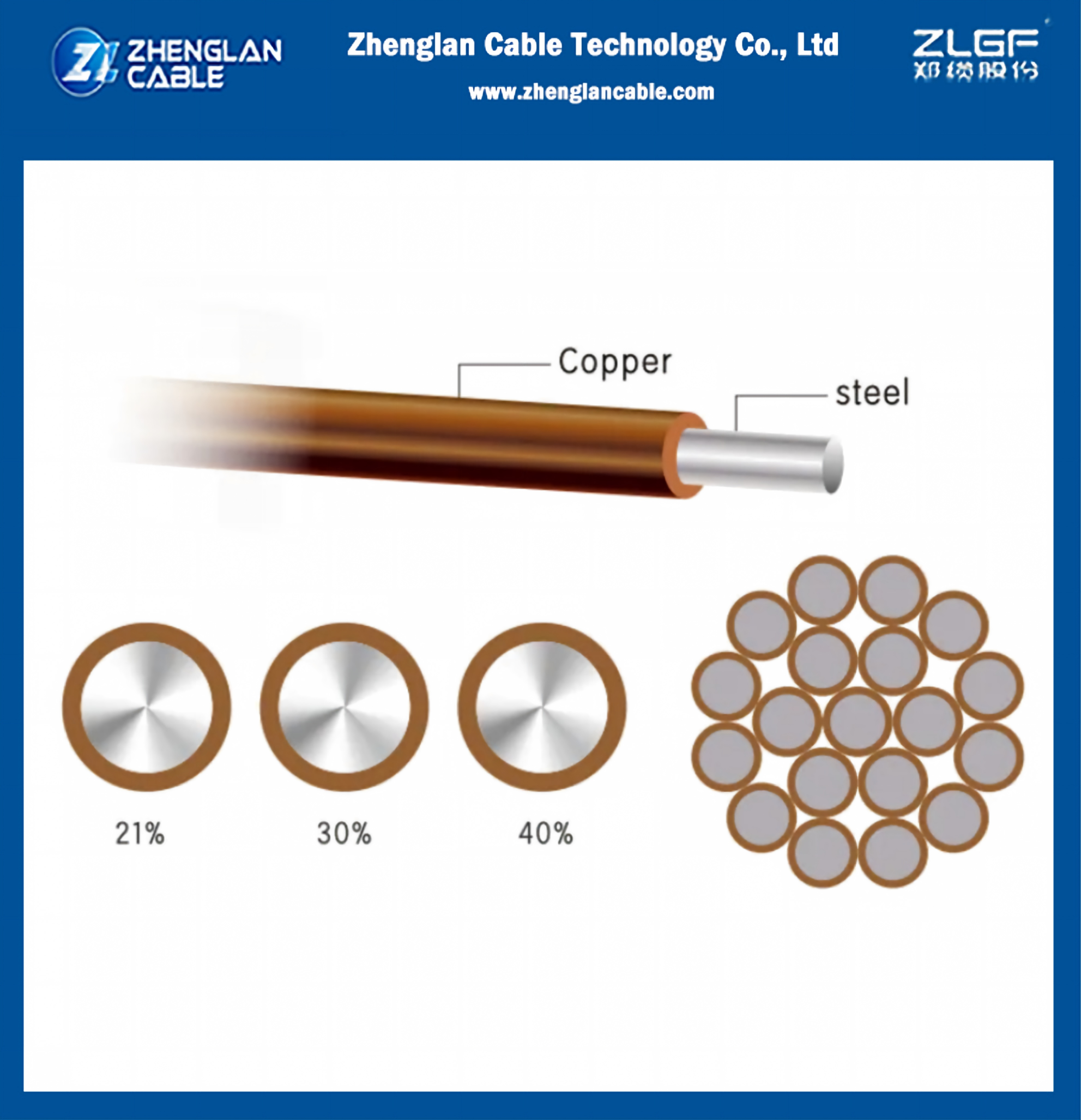
Copperclad Steel Wire is a strong, non-rusting, efficient grounding conductor. It is composed of Coppercladding that is permanently bonded to the central steel core of each wire. Copperclad provides the same conductivity and corrosion resistance as copper while maintaining the high strength of steel. Dead Soft Annealed (DSA) Copperclad Steel Wire is very flexible for easy preparation and installation. When compared to solid copper, Copperclad Steel Wire has faster impedance to ground for better protection of lines and equipment plus a higher resistance to thermal expansion failures. It also reduces the fatigue damage caused by more than 10 times that of annealed solid copper. Copperclad Steel Wire is an excellent solution for areas with high rates of copper theft as the amount of copper used in the bonding process is minimal—6% to 10% depending on the conductivity. When Copperclad Steel Wire is used in place of copper, the grounding conductor is far less likely to be stolen. This feature is important not only from an economic standpoint, but also from the standpoint of safety and reliability. Often, the fact that a copper downlead has been removed is not evident until a surge current causes a failure in the system. Copperclad Steel Wire (CCS Wire) Application Cases Case 1: Power Grid Substation & Transmission Tower Grounding (Global Utility Projects) Project Background Large 35kV/110kV/220kV outdoor substations and mountain overhead transmission towers. Local areas suffer severe copper cable theft; pure copper down-leads were frequently stolen, causing lightning surge failures and unplanned power outages. Traditional solid copper wire also cracked easily under long-term soil extrusion and thermal expansion cycles.Solution AdoptedDead Soft Annealed Copperclad Steel Wire as main grounding down-leads and grid connecting conductors. Copper coating ratio 8%–10% to match copper conductivity.Project OutcomesAnti-theft effect: Minimal copper content makes scrap value negligible, zero theft incidents after 4 years operation.Mechanical performance: 10x higher fatigue resistance than solid copper; no fracture under thermal expansion & ground settlement stress.Electrical safety: Lower ground impedance, lightning surges dissipate faster, transformer & switchgear damage rate dropped by over 70%.Cost benefit: Total project material cost cut by 40% vs full solid copper grounding system. Case 2: Solar & Wind Renewable Energy Power Stations (Coastal & Inland PV Plants)Project Background Large-scale photovoltaic farms and onshore wind turbine bases. Harsh environments: coastal salt fog, rocky mountain soil, strong wind vibration. Pure copper wire is soft, easy to deform and snap during trenching; frequent copper theft at remote unattended solar sites brought huge maintenance losses.Solution AdoptedDSA copperclad steel wire for PV array grounding, wind turbine tower earthing conductors. High tensile steel core adapts to rocky burial and long-distance overhead laying.Project OutcomesCorrosion resistance: Copper cladding prevents electrochemical corrosion under salt & acid soil, stable grounding resistance ≤4Ω all year round.Construction advantage: DSA soft grade flexible for bending around brackets, installation speed improved by 15% compared with rigid solid copper.Anti-theft security: Remote unmanned stations no longer face grounding wire theft; annual maintenance repair costs reduced significantly. From power transmission to renewable energy, communication infrastructure to public transit, CCS wire balances electrical performance, mechanical durability, anti-theft safety and overall project cost. It has become a reliable, long-service-life grounding solution for all kinds of outdoor, remote and harsh-environment earthing projects.
2026/07/17

A Brief Introduction to UL Flame Retardant Ratings

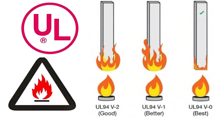
UL (Underwriters Laboratories), founded in 1894, is a global safety certification organization with over a century of history. Its standards are widely recognized, especially in the US market, and many retailers and buyers consider UL certification a prerequisite for product market access. UL certification indicates that a product has reached a certain level of safety, performance, and quality, effectively protecting consumers' lives and property. Overview of UL 94 Flame Retardant Rating UL 94 is a flammability testing standard for plastic materials established by Underwriters Laboratories (UL). It is a widely used global standard for evaluating the flammability of plastics. This standard evaluates a material's ability to extinguish itself after being ignited, based on factors such as burning rate, burning time, drip resistance, and whether the drips burn. UL94 Flame Retardancy Rating ClassificationUL94 is divided into 12 ratings, arranged from lowest to highest flame retardancy. Rating Type Description HB Horizontal Burning Lowest flame retardancy rating, suitable for materials with low flame retardancy requirements V-2 Vertical Burning Allows dripping molten material V-1 Vertical Burning Allows dripping molten material, but self-extinguishing time is longer than V-0 V-0 Vertical Burning Common highest rating, no dripping molten material allowed 5VB 5V Burning Allows the test piece to be penetrated by the flame 5VA 5V Burning Highest rating, no penetration allowed VTM-0/VTM-1/VTM-2 Film Materials Suitable for plastic films HBF/HF1/HF2 Foamed Materials Applicable to foamed materials Rating Criteria for Each Grade HB Grade (Horizontal Combustion)Sample thickness requirement: 1.5mm to 13mm; Combustion rate: less than or equal to 40mm/min or 75mm/min; Combustion ceases before the 100mm mark. V-0 (Vertical Burning): After 10 seconds of flame combustion, the test piece must not ignite for more than 10 seconds; total burning time must not exceed 50 seconds; no dripping is allowed. V-1 (Vertical Burning): Self-extinguishing time requirement is longer than V-0; dripping is allowed. V-2 (Vertical Burning): Dripping of burning material is allowed; flame retardant requirements are lower than V-1. 5VA/5VB (5V Burning): After 5 seconds of flame combustion, the test piece must not ignite for more than 60 seconds.    5VA: The test piece must not be penetrated by the flame.    5VB: The test piece is allowed to be penetrated by the flame. Test Methods UL94 includes several test configurations: Horizontal Burning Test (HB) - The most basic test Vertical Burning Test (V-0/V-1/V-2) - The most commonly used 5V Test (5VA/5VB) - A more stringent test Thin Film Test (VTM-0/VTM-1/VTM-2) - Applicable to thin film materials Foamed Material Test (HBF/HF1/HF2) - Applicable to foamed materials Application Areas UL94 test results are commonly used in the following industries:Electronics and Electrical AppliancesAutomotiveConstructionEnergy Storage Important Notes A higher UL94 rating indicates stronger flame retardancy, but a higher rating is not always better. The UL94 rating should be selected based on the material's application scenario and performance requirements, and testing should be conducted at different thicknesses to ensure product safety under various conditions. This standard does not apply to building and decorative materials.
2026/06/30

Selection of Cable Core for Voltage Levels of 1kV and Below

In long-distance lines or high-current circuits, single-core cables are recommended to reduce intermediate joints and save costs. Furthermore, single-core cables are also suitable for low-voltage DC power supply circuits.   At voltage levels of 1kV and below, if the power supply neutral point is directly grounded and the protective conductor and neutral conductor share the same conductor in a single-phase circuit, a 2-core cable should be selected. For DC power supply circuits, a 2-core cable is also recommended. Of course, depending on specific grounding and current requirements, 3-core and 4-core cables are also available.   4-core cables (3+1 structure) for 1kV and below not only use the fourth core for protective grounding but also bear the important task of transmitting unbalanced current and short-circuit current in the power system. Their specifications need to be determined based on the actual requirements of unbalanced current and short-circuit current, but generally should not be less than 1/2 of the phase conductor's current carrying capacity. In low-voltage power distribution systems of 1kV and below, if a three-phase four-wire system is used, and the protective earth (PE) and neutral (PN) conductors share the same conductor, a 4-core cable must be selected to avoid power frequency interference problems caused by non-standard configurations.   For electrical installations with extremely high safety requirements, and for communication centers and automation equipment that require simultaneous electrical safety and interference-resistant grounding, a 5-core TN-C low-voltage power distribution system is recommended. This allows the protective earth (PE) and neutral (PN) conductors to operate independently, with their core cross-sectional areas typically being 3 large and 2 small, 4 large and 1 small, or 5 large, ensuring independent PE and PN conductors and providing reliable grounding and interference immunity.
2026/05/30
1 2 3 4 5 6 7 8 9 10
Privacy Policy | China Good Quality Aluminum Power Cable Supplier. Copyright © 2019-2026 Zhenglan Cable Technology Co., Ltd . All Rights Reserved.