logo
player background
live avator

5s
Total
0
Today
0
Total
0
Today
0
  • What would you like to know?
    Company Advantages Sample Service Certificates Logistics Service
Online Chat WhatsApp Inquiry
Auto
resolution switching...
Submission successful!
Zhenglan Cable Technology Co., Ltd
Products
News
Home >

China Zhenglan Cable Technology Co., Ltd Company News

Contacts
Contacts: Miss. Linda Yang
Fax: 86-371-61286032
Contact Now
Mail Us

Cable Length Calculation – Check if any allowances are omitted

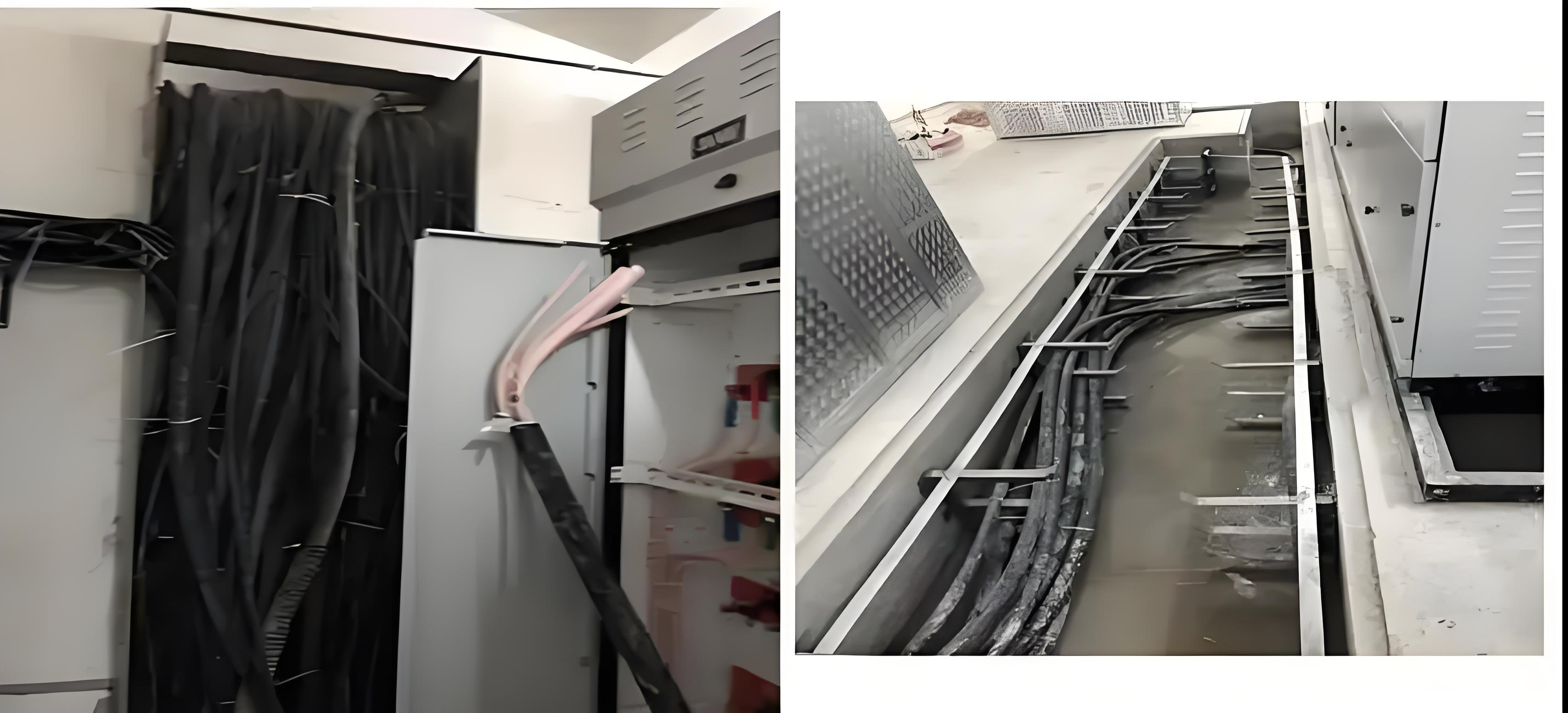
1. Rules for Cable Length Calculation During cable installation, whether routed through conduits or cable trays, cables are not installed in a fully taut condition. Allowances must be made for slack, waveform curvature and crossings. According to calculation specifications, the laying allowance factor is 2.5%. Total cable length = (Total straight cable length + Reserve lengths) × 1.025 2. Calculation of Reserve Lengths Note: Additional and reserve lengths form an integral part of installed cable length and shall be included in the measured quantity. In other words, the extra length for laying slack, waveform curvature and crossings shall be calculated based on the sum of horizontal & vertical routing lengths shown on drawings plus all applicable reserve lengths. 01. Cable slack, waveform curvature and crossings An allowance factor of 2.5% shall be applied to the overall length to account for cable slack, waveform curvature and crossings. 02. Cables entering buildings For external cables along municipal roads (or traffic safety engineering cables) entering a site, a minimum reserve of 2 m shall be considered. 03. Cables entering trenches or cable hangers Minimum vertical lead-in / lead-out reserve: 1.5 m where cables enter trenches or hangers. 04. Incoming and outgoing cables at substations Minimum reserve: 1.5 m. 05. Cable terminations Minimum reserve of 1.5 m for power cable terminations for maintenance purposes. 06. Cable intermediate joints A reserve of 2 m shall be left at each side of every cable joint box for maintenance. 07. Cables entering control panels, protection panels, mimic panels, distribution boxes, etc. The reserve length equals the perimeter half of the panel / box face (height + width). 08. High-voltage switchgear and low-voltage distribution panels / boxes For cables routed in and out below panels, a reserve of 2 m shall be provided. 09. Cables to motors Starting from the motor terminal box, add a reserve of 0.5 m. 10. Station service transformers A reserve of 3 m measured from finished floor level. 11. Cables routed around beams, columns and other structures Additional length shall be calculated according to the cross-section dimensions of the structures bypassed. 12. Elevator cables fixed to cable brackets A reserve of 0.5 m at each fixing point
2026/08/14

Cable Length Calculation – Check if any allowances are omitted

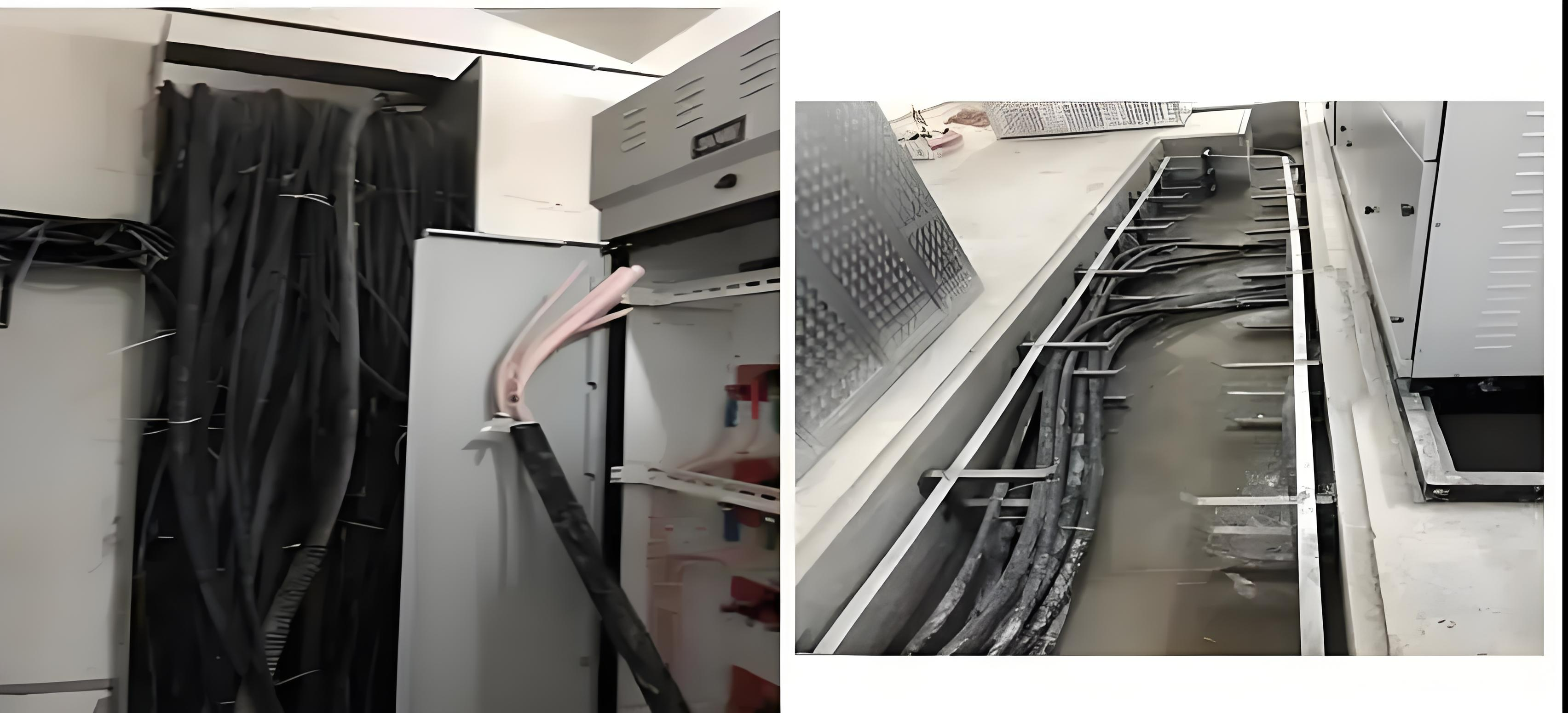
1. Rules for Cable Length Calculation During cable installation, whether routed through conduits or cable trays, cables are not installed in a fully taut condition. Allowances must be made for slack, waveform curvature and crossings. According to calculation specifications, the laying allowance factor is 2.5%. Total cable length = (Total straight cable length + Reserve lengths) × 1.025 2. Calculation of Reserve Lengths Note: Additional and reserve lengths form an integral part of installed cable length and shall be included in the measured quantity. In other words, the extra length for laying slack, waveform curvature and crossings shall be calculated based on the sum of horizontal & vertical routing lengths shown on drawings plus all applicable reserve lengths. 01. Cable slack, waveform curvature and crossings An allowance factor of 2.5% shall be applied to the overall length to account for cable slack, waveform curvature and crossings. 02. Cables entering buildings For external cables along municipal roads (or traffic safety engineering cables) entering a site, a minimum reserve of 2 m shall be considered. 03. Cables entering trenches or cable hangers Minimum vertical lead-in / lead-out reserve: 1.5 m where cables enter trenches or hangers. 04. Incoming and outgoing cables at substations Minimum reserve: 1.5 m. 05. Cable terminations Minimum reserve of 1.5 m for power cable terminations for maintenance purposes. 06. Cable intermediate joints A reserve of 2 m shall be left at each side of every cable joint box for maintenance. 07. Cables entering control panels, protection panels, mimic panels, distribution boxes, etc. The reserve length equals the perimeter half of the panel / box face (height + width). 08. High-voltage switchgear and low-voltage distribution panels / boxes For cables routed in and out below panels, a reserve of 2 m shall be provided. 09. Cables to motors Starting from the motor terminal box, add a reserve of 0.5 m. 10. Station service transformers A reserve of 3 m measured from finished floor level. 11. Cables routed around beams, columns and other structures Additional length shall be calculated according to the cross-section dimensions of the structures bypassed. 12. Elevator cables fixed to cable brackets A reserve of 0.5 m at each fixing point
2026/08/14

The advantages and disadvantages of aluminum conductor aluminum alloy reinforced

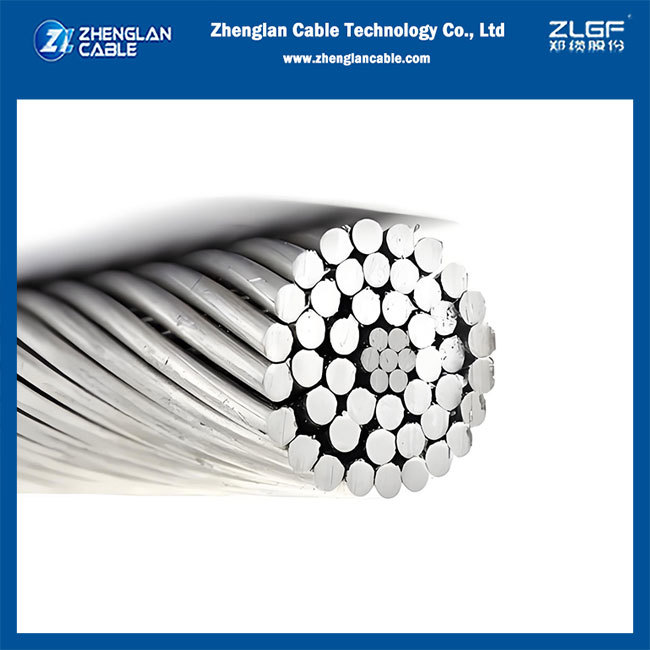
Aluminum conductor aluminum alloy reinforced (ACAR) is a composite conductor that uses a high-strength aluminum alloy core instead of a steel core, with an outer layer of highly conductive aluminum strands. Its core advantages lie in reducing resistance loss and vertical load. Its main drawbacks are lower tensile strength compared to steel core aluminum stranded wire and a larger wind deflection angle in strong winds.   Main Advantages: Energy Saving and Consumption Reduction: Replacing the steel core (with a conductivity of only ~9% IACS) with an aluminum alloy core (with a conductivity of approximately 52.5%~53%) increases the effective conductive cross-section, significantly reducing DC resistance and minimizing line power loss. Superior Sag Characteristics: Under the same outer diameter and tension conditions, sag is smaller or comparable, which helps reduce tower height requirements (approximately 3 meters in some projects). Lightweight and Low Load: With a lower density than steel core structures, the vertical load is reduced by approximately 10%, making it more stress-friendly for foundations and tower materials, suitable for capacity expansion or geologically restricted areas. No Hysteresis/Eddy Current Loss: The core is made of non-ferromagnetic material, eliminating the additional losses caused by the alternating magnetic field of a steel core. Good Corrosion Resistance:The aluminum alloy core is more resistant to atmospheric corrosion than galvanized steel cores, exhibiting excellent lifespan, especially in non-extremely polluted areas.   Main Disadvantages: Lower Mechanical Strength: Its tensile strength is lower than that of aluminum-coated steel (ACSR), making it unsuitable for applications requiring extremely high tensile strength, such as long crossings or heavy icing areas. Larger Wind Deflection Angle: Due to its light weight and relatively low stiffness, the wind deflection angle is 2°~3° larger than that of aluminum-coated steel of the same specifications under high wind conditions, requiring calibration of electrical clearances. Higher Cost: The cost of aluminum alloy materials and manufacturing processes is higher than that of ordinary steel cores, resulting in slightly higher initial investment. Limited Heat Resistance: The heat resistance temperature of conventional aluminum alloy cores typically does not exceed 80~100℃ (unless a special heat-resistant alloy is used), limiting the improvement of high-temperature current carrying capacity. Recommended Application Scenarios Recommended: Capacity upgrades and renovations of existing power lines, medium-span high-voltage transmission lines, corrosive environments (excluding strong salt spray), and lines sensitive to line loss. Use with Caution: Long crossings, heavy icing areas, strong wind areas, or ultra-high-voltage trunk lines with extremely high mechanical strength requirements.
2026/08/10

Robots Win Half Marathon, Cable Industry Reaches New Heights

The successful completion of a half marathon by a humanoid robot is not only a milestone breakthrough in intelligent movement capabilities, but also the ultimate test of the extreme bending resistance and high-frequency torsional resistance of the internal dynamic cables. Continuous running, high-frequency joint twisting, and repeated bending in confined spaces rendered ordinary cables obsolete, forcing the entire cable industry to leap from general manufacturing to high-flexibility, high-reliability specialty cables. Domestic cable companies, through material innovation and breakthroughs in structural processes, have rapidly achieved mass production and import substitution, becoming the core support behind the robotics industry. I. Half Marathon-Level Sport: The Ultimate Test of Cable Bending and Torsion Performance The robot's continuous running process is equivalent to placing an extremely rigorous endurance test on the internal cables. In high-speed reciprocating motion, the cables must withstand millisecond-level repeated bending and high-frequency torsional movements at all angles. Ordinary cables are prone to core wire breakage, outer sheath cracking, and signal transmission interruption, making them completely unable to support long-distance, high-intensity dynamic operation. This "test" placed almost stringent requirements on cables: * **Ultra-small bending radius:** Due to the compact space of robot joints, the bending radius of the cable needed to be compressed to 5-8 times its outer diameter, making conventional cables unsuitable. * **Ultra-high torsional life:** The legs and torso needed to achieve continuous torsion of ±180°~±360°/meter, with a bending life exceeding 10 million cycles without failure. * **Stable dynamic transmission:** Power and signal were transmitted synchronously, with stable electromagnetic shielding performance, eliminating transmission interruptions caused by running, jumping, and vibration. * **Lightweight and robust:** Balancing the need for weight reduction with wear and weather resistance, suitable for long-distance continuous outdoor operation. II. Technological Breakthrough: The Cable Industry's Core Solution Faced with the extreme working conditions of robotic scenarios, the domestic cable industry focused on overcoming the challenges of bending and torsion from three dimensions: conductor, structure, and materials, achieving a generational technological upgrade. In terms of core technologies, the industry has achieved several key breakthroughs: the use of multi-strand twisted Class 6 ultra-fine copper wires and optimized pitch ratio design significantly improves fatigue resistance and effectively prevents repeated bending and breakage; the golden helix angle structure combined with an aramid tensile reinforcement layer disperses torsional stress, solving the problems of core wire displacement and sheath cracking; high-performance elastic materials such as PUR and TPU replace traditional PVC sheaths, improving wear resistance and weather resistance, and preventing embrittlement at low temperatures; and a layered composite shield composed of tin-plated copper wire braid and aluminum foil ensures stable signal transmission during high-speed movement, achieving industrial-grade anti-interference capabilities. III. Industry Leap Forward: From Supporting and Following to High-End Leadership The robot completing a half-marathon, seemingly a technology demonstration, is actually a vivid microcosm of the value upgrading of the cable industry. The industry's development focus is rapidly shifting from low-margin general-purpose cables to high-value-added specialty flexible cables, with related product gross profit margins increasing to over 35%. Domestic cable manufacturers have achieved independent R&D across the entire chain, from basic materials to structural design, gradually reducing reliance on foreign suppliers for key products and providing a solid guarantee for the localization of humanoid robots and high-end intelligent manufacturing equipment. Performance indicators, with bending and torsion resistance as the core, are becoming important entry barriers for the industry, driving the entire cable industry towards precision, customization, and high performance. Conclusion A robot winning a half-marathon is essentially a real "stress test" of cable bending and torsion technology. Cables, once considered supporting components, have now become a core factor determining the robot's mobility. Through continuous technological breakthroughs and scenario-based implementation, China's cable industry is achieving a crucial leap from scale leadership to technological dominance, laying a solid foundation for China's robot industry to participate in global competition.
2026/07/03
1 2 3 4 5 6 7 8 9 10
Privacy Policy | China Good Quality Aluminum Power Cable Supplier. Copyright © 2019-2026 Zhenglan Cable Technology Co., Ltd . All Rights Reserved.