logo
Zhenglan Cable Technology Co., Ltd
Products
News
Home >

China Zhenglan Cable Technology Co., Ltd Company News

Contacts
Contacts: Miss. Linda Yang
Fax: 86-371-61286032
Contact Now
Mail Us

How to properly select cables for photovoltaic systems?

In recent years, the technology of the photovoltaic industry has developed faster and faster. The power of a single module is getting bigger and bigger, and the current of the string is getting bigger and bigger. The current of high-power modules has reached more than 17A. In terms of system design, the use of high-power components and reasonable reserved space can reduce the initial investment cost and kilowatt-hour cost of the system. The cost of AC and DC cables in the system is not low. How should we design and select to reduce costs?   1. Selection of DC cables DC cables are installed outdoors. It is generally recommended to select irradiated and cross-linked photovoltaic cables. After high-energy electron beam irradiation, the molecular structure of the cable insulation material changes from a linear type to a three-dimensional mesh molecular structure, and the temperature resistance level increases from 70℃ for non-cross-linked cables to 90℃, 105℃, 125℃, 135℃, and even 150℃, which is 15-50% higher than the current carrying capacity of cables of the same specification. It can withstand drastic temperature changes and chemical erosion and can be used outdoors for more than 25 years. When choosing a DC cable, you should choose a product with relevant certification from a regular manufacturer to ensure long-term outdoor use. The most commonly used photovoltaic DC cable is the 4-square cable of PV1-F1*4, but with the increase in the current of photovoltaic modules and the increase in the power of a single inverter, the length of the DC cable is also increasing, and the application of 6 square meters of DC cables is also increasing.   According to relevant specifications, it is generally recommended that the loss of photovoltaic DC should not exceed 2%. We use this standard to design how to choose DC cables. The line resistance of PV1-F1*4mm² DC cable is 4.6mΩ/meter, and the line resistance of PV6mm² DC cable is 3.1mΩ/meter. Assuming the working voltage of the DC component is 600V, the 2% voltage drop loss is 12V. Assuming the component current is 13A, using 4mm² DC cable, the distance between the farthest end of the component and the inverter is recommended not to exceed 120 meters (single string, excluding positive and negative poles). If it is greater than this distance, it is recommended to select a 6mm² DC cable, but it is recommended that the distance between the farthest end of the component and the inverter should not exceed 170 meters.   2. Calculation of photovoltaic cable line loss To reduce system costs, the components and inverters of photovoltaic power stations are rarely configured in a 1:1 ratio but are designed with a certain over-matching according to lighting conditions, project needs, etc. For example, for a 110KW module, a 100KW inverter is selected. According to the calculation of 1.1 times the over-matching of the inverter AC side, the maximum AC output current is about 158A. The AC cable can be selected according to the maximum output current of the inverter. Because no matter how many components are configured, the AC input current of the inverter will never exceed the maximum output current of the inverter.   3. Inverter AC output parameters Commonly used photovoltaic system AC copper cables include BVR and YJV. BVR means copper core polyvinyl chloride insulated soft wire, YJV cross-linked polyethylene insulated power cable. When selecting, pay attention to the voltage level and temperature level of the cable. Flame-retardant type should be selected. Cable specifications are expressed by the number of cores, nominal cross-section, and voltage level: single-core branch cable specification expression method, 1*nominal cross-section, such as 1*25mm 0.6/1kV, indicating a 25 square cable. Multi-core twisted branch cable specification expression method, the number of cables in the same loop*nominal cross-section, such as 3*50+2*25mm 0.6/1KV, indicating 3 *50 square live wires, 1* 25 square neutral wire, and 1* 25 square ground wire.
2025/02/22

Product series of power cables

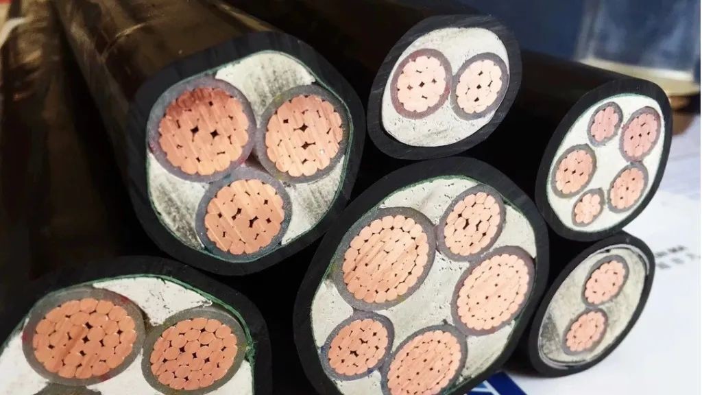
Polyvinyl chloride insulated power cables: Polyvinyl chloride plastics are cheap, have good physical and mechanical properties, and have simple extrusion processes, but their insulation properties are average. They are used in large quantities to manufacture low-voltage power cables of 1 kV and below for use in low-voltage distribution systems. If insulating materials with voltage stabilizers are used, 6 kV cables can be produced.   Cross-linked polyethylene insulated power cables: Good electrical properties, mechanical properties and heat resistance. In the past two decades, it has become the leading variety of medium and high voltage power cables in my country, and can be used in various voltage levels from 6 to 330 kV. In recent years, cross-linking of 1 kV low-voltage cables has become a technical direction. The key is to reduce the insulation thickness so that it can compete with polyvinyl chloride cables in terms of price.   Viscous oil-impregnated insulated power cables: They were the leading products of medium-voltage cables in my country before 1992. This is a classic structure of power cables with a history of more than 100 years, with large electrical and thermal performance margins and long service life. Oil-filled cable: suitable for 66-500 kV. Rubber insulated power cable: a soft, movable power cable, mainly used in places where enterprises often need to change the laying position. Natural rubber insulation is used, the voltage level is mainly one kV, and 6 kV level can be produced. Overhead insulated cable: essentially an overhead conductor with insulation, the insulation can be made of polyvinyl chloride or cross-linked polyethylene. Generally made into a single core, or 3-4 phase insulated cores can be twisted into a bundle without sheath, which is called a bundled overhead cable.   Characteristics of power cables:   Compared with other overhead bare wires, its advantages are less affected by external climate, most reliable, concealed, less maintenance, durable, and can be laid in various occasions. However, the structure and production process of power cables are relatively complex and the cost is relatively high.   Different specifications, but all have the following characteristics and manufacturing requirements:   The working voltage is high, so the cable is required to have excellent electrical insulation performance.   The transmission capacity is large, so the thermal performance of the cable is more prominent.   Since most of them are fixedly laid in various environmental conditions (underground, tunnel trenches, shaft slopes, and underwater, etc.), and require reliable operation for decades, the requirements for sheath materials and structures are also high.   Due to changes in factors such as power system capacity, voltage, number of phases, and different laying environmental conditions, the varieties and specifications of power cable products are also quite numerous. According to the strong electrical characteristics of power cable applications, the consideration of its electrical and mechanical properties is relatively prominent.
2025/02/21

Cable designation codes in German standards

The designation codes in different country for different type of cable are different in each country. Below are parts of the Designation Codes for cable designation in Germany.   Reference standards DIN VDE 0292 Type Designation Codes for cable designation DIN VDE 0293-308 Identification of the cores of cables / wires and flexible wires by colors Standard series DIN VDE 0281 for PVC-insulated cables Standard series DIN VDE 0282 for rubber insulated cables Designation Codes for Plastic insulated Power Cables Power cables with plastic insulation and plastic sheath according to DIN VDE 0262, DIN VDE 0263, DIN VDE 0265, DIN VDE 0266, DIN VDE 0267, DIN VDE 0271, DIN VDE 0273 and DIN VDE 0276 part 603, 604, 620, 622, 626 For cables with plastic insulation and plastic sheath the following designation codes are used (starting with the conductor): Code Description N Cables acc. to standard A Aluminum conductor Y Insulation of polyvinyl chloride (PVC) 2Y Insulation of thermoplastic polyethylene (PE) X Insulation of cross-linked polyvinyl chloride (XPVC) 2X Insulation of cross-linked polyethylene (XLPE) H Field limiting conductive layers over the conductor and over the Insulation HX Insulation of cross-linked halogen-free polymer blend C Concentric conductor of copper CW Concentric conductor of copper, waveform (ceander) CE Concentric conductor in multi-core cables on each individual core S Braided copper SE For multicore cables field limiting conductive layers over the conductor and the insulation and copper screen over each individual core (indicated by “H” is omitted here) F Overhead line cable (DIN VDE 0276) F Armouring of galvanized flat steel wire FE insulation sustaining (F) Longitudinally watertight cable (screen) B Steel tape armouring R Armouring of galvanized round steel wires G Helix of galvanized steel tape HX Sheath of cross-linked halogen-free polymer blend Y Inner sheath of polyvinylchloride (PVC) Y Outer sheath of polyvinylchloride (PVC) 2Y Outer sheath of polyethylene (PE) 1Y Outer sheath of polyurethane (PUR)   Conductor cross-section, shape and structure Code Description R Circular conductor S Sector shaped conductor E Solid conductor M Stranded conductor RE Circular conductor, solid RM Circular conductor, stranded SE Sector shaped conductor, solid SM Sector shaped conductor, stranded OM Oval shaped conductor, stranded H Waveguide /V Compacted conductor  
2025/02/08

Relationship between DC resistance and cross-section of compressed copper conductor

  In practical applications, the design of compressed copper conductors needs to consider many factors, including compression coefficient, stranding structure, material resistivity, etc.   For example, for a 95 mm² compressed copper conductor, its kilometer resistance should not exceed 0.193Ω/km, which needs to be achieved through a reasonable stranding structure and single wire diameter.   The compression process will increase the resistivity of the conductor, so it is necessary to introduce corresponding correction factors during design, such as compression coefficient K3 and stranding coefficient K2, to ensure that the final resistance value meets the standard requirements.     The relationship between the cross-sectional area and DC resistance of compressed copper conductors can be summarized by the following points: 1. Inverse relationship: The cross-sectional area A is inversely proportional to the DC resistance R, that is, the larger the cross-sectional area, the smaller the DC resistance. 2. Compression effect: The compression process will cause the conductor to harden, thereby increasing the resistivity, which needs to be adjusted through the correction factor. 3. Design requirements: According to national standards (such as GB/T3956), the DC resistance value of the conductor is the key indicator to measure its qualification, and the cross-sectional area is only the basis for design and calculation. 4. Adjustment in practical application: In the production process, in order to reduce costs, the cross-sectional area may be reduced to the minimum value to meet the DC resistance requirements, but this practice may affect the overall performance of the cable.   Therefore, when designing and manufacturing compressed copper conductors, it is necessary to comprehensively consider factors such as cross-sectional area, compression coefficient, and material resistivity to ensure that the DC resistance of the conductor meets the standard requirements and meets the performance requirements in practical applications.   The specific calculation method of the compression coefficient K3 and twisting coefficient K2 of the compressed copper conductor is as follows: Compression coefficient K3: Compression coefficient K3 refers to the ratio of the actual cross-sectional area of ​​the conductor after compression to the theoretical cross-sectional area when not compressed. According to the evidence, the value of the compression coefficient is usually 0.90, which is empirical data based on production experience and process tests.   Twisting coefficient K2 : The twisting coefficient K2 refers to the ratio of the actual length of a single wire to the length of the twisted wire pitch within a twist pitch. Other related parameters 1. Single wire diameter: For stranded conductors with a single wire diameter greater than 0.6 mm, K2 is 1.02; for stranded conductors with a single wire diameter not greater than 0.6 mm, K2 is 1.04. 2. Cabling coefficient: For single-core and non-cabled multi-core cables, it is 1, and for cabled multi-core cables, it is 1.02.   In summary, the specific calculation method of the compaction coefficient K3 and twisting coefficient K2 of compacted copper conductors is as follows: Compressive coefficient K3: Usually the value is 0.90.
2025/01/08
1 2 3 4 5 6 7 8 9 10
Privacy Policy | China Good Quality Aluminum Power Cable Supplier. Copyright © 2019-2025 Zhenglan Cable Technology Co., Ltd . All Rights Reserved.